
4-channel surge protector ECO series in box for IP with PoE
- Add feedback:
- Code: PTF-4-ECO/PoE
-
Availability:
 Product discontinued
4-kanałowy moduł zabezpieczenia przeciwprzepięciowego dla skrętki UTP i PTF serii ECO, z ochroną zasilania PoE, model PTF-4-ECO/PoE. Dedykowany dla urządzeń końcowych, montowanych wewnątrz pomieszczeń.
Product discontinued - has been replaced by PTF-54-ECO/PoE
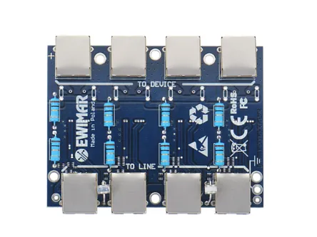
The PTF-4-ECO / PoE is a 4-channel device that combines a 5 cat UTP cable system with overvoltage protection, LAN protection, and a PoE power supply line protection from lightning strikes. The system is based on 4-channel replaceable modules, which can be freely selected to create the most optimal device for the needs of each installation.
The ECO series is recommended for CCTV installations in which end devices (cameras, recorders, switches) are located inside the building. To protect external cameras mounted on posts or roofs, use PRO or Extreme panels.
The ECO series is recommended for CCTV installations in which end devices (cameras, recorders, switches) are located inside the building. To protect external cameras mounted on posts or roofs, use PRO or Extreme panels.


Protection consists of suppress of ion low-power ESD pulses (ionizing jets) and pulses induced between individual UTP wires during discharges.
These pulses have a destructive effect on the Ethernet interface amplifiers, despite the use of the galvanic isolation used on the hardware layer.
These pulses have a destructive effect on the Ethernet interface amplifiers, despite the use of the galvanic isolation used on the hardware layer.
The PTF-4-ECO / PoE is specifically designed for CCTV powered by PoE switches. For the power supply, pins 4,5 and 7,8 are connected to each other to increase the current flowing through the protection circuit. Due to the limited power of decoupling resistors, the maximum power of the powered devices should not exceed 30W at 48V. The decoupling resistors protect the protective components against damage in the event of a longer overvoltage and allow the protection to be graduated.
In order to achieve full efficiency of the device, it is required to connect to a grounding or PE conductor. It is not recommended to connect the grounding wire to the lightning protection system of the building.

Block diagram
Specifications:
| PARAMETR NAME | VALUE |
| DATA LINE | |
|---|---|
| Number of channels | 4 |
| Category | 100Base-T(100Mbit) network, using 5/5e/6 category twisted-pair |
| Levels of protection | 2 (Air ionizing, Bridge Transil) |
| Capacity line to line | 6-8pF @ 0V, 1Mhz |
| Capacity line to ground | < 1pF |
| Protection level line to line | 6V-1kV, 20V @ 100A , 8/20uS Vc |
| Maximum Uc voltage | 6,8V |
| Maximum power 8 / 20us (line to line) | 2kW |
| PoE LINE | |
| Number of channels | 4 |
| Levels of protection | 2 (Air ionizing, Bridge Transil) |
| Protection level line to line for PoE 10/1000uS | 600W / 100A, 10/1000uS |
| Maximum Uc voltage PoE | 58V |
| Protection level line to ground | 90V-4kV, 2~4kA, 8-20uS |
| Maximum voltage line to ground | 90VDC |
| PoE work standard | Complies with IEEE 802.3af of type B |
| OTHER | |
| Input connector (line) | RJ-45 |
| Output connector | RJ-45 |
| Output ground | Yes - dla iskrowników jonizujących |
| Fixing | Rack 19" 1U or plastic housing |
| Additional options | Replacable modules of different types, top cover |
| Dimensions | 100 x 75 x 15 (mm) |
| Operating temperature | -30~+60° |