How to choose the surge arresters correctly?
In order to choose the right surge protection system, it is necessary to know many factors that influence the level of danger:
- Place of installation of protected devices - inside or outside the building, metal structure
- The extent, structure, length and type of cabling, cable routing
- Types of interfaces, types of signals, supply voltage and rated loads
Each of the arresters has a number of parameters that determine its suitability for use in a given installation. Knowing the level of danger and the properties of the signals of the devices that are protected, you should select a protective device with a response voltage slightly higher than the voltages that may arise during operation. The construction of the protective device, the number of protective stages, the types of components and the technology used are also important. You should carefully compare the parameters, which can also vary significantly depending on the shock pulse shape that was used in their testing - depending on the pulse shape given, the values can vary greatly.
1. Selection of voltage parameters
The arrester has nominal and maximum voltage parameters which decide to which signal sources they can be applied. The use of surge arresters with voltage parameters much higher than the actual signals will cause too high voltage surge to pass through it and the risk of damaging the protected device. The use of a arrester with voltage parameters equal to or below the appropriate signals may trigger the device and interfere with the operation of the protected device.

Un (line-line) - nominal line-line voltage for which the surge arrester is designed. This is the voltage that can normally be transmitted through the arrester, without causing the device to trigger and not hindering the operation of the protected device.
Uc (line-line) - maximum continuous line-line voltage. The voltage sent by the limiter may fluctuate as a result of changes in the power supply, data transmission or bus load. Exceeding the maximum continuous operating voltage causes the arrester to trigger.
Uc (line-ground) - maximum line to ground voltage. It is the maximum potential in relation to the ground that may appear on the protected conductor - when it is exceeded, the arrester is activated. It appears at the moment of a spark over and causes the shock charge to discharge to the ground, which prevents high voltage and current from flowing through the protected device.
Up (line-line) - voltage of the line-to-line protection level. There is a maximum voltage to which the arrester will reduce the surge voltage when an overvoltage occurs. The parameter is given for the maximum surge current that the arrester is able to transfer without damaging it for a given pulse shape.
Up (line-ground) - voltage of the line-to-ground protection level. There is the maximum voltage in relation to the ground to which the limiter will reduce the surge voltage when an overvoltage occurs. The parameter is given for the maximum surge current that the arrester is able to transfer without damaging it for a given pulse shape.
When selecting the arrester in terms of voltage, it should be noted that the value of alternating voltage is given as the effective voltage. In fact, the instantaneous peaks are much higher - for example, 230VAC actually has a peak of 325Vp-p, and the tolerance of this voltage rise must also be considered. A similar situation is also in the case of transmission lines, whose peak voltages can only be measured with special devices or an oscilloscope. Taking into account the tolerance of these voltages, it is best to consult the device manufacturer regarding the selection of the arrester or to use protectors dedicated to specific types of current (direct, alternating) as well
as digital buses and analog signals.
2. Selection of current parameters
The current parameters determine the resistance of the surge arrester to the value of the surge current, so they are the most crucial in terms of protective effectiveness. Classes of protective devices are described in the PN-EN 61643-21: 2004 standards, but they do not take into account many modern solutions developed in recent years, which have a very high protection efficiency and many benefits for fast digital transmissions. An example is the MOSFET components used by Ewimar, which enable the use of some low-power and low-loss components.

IN / IN-MAX - nominal and maximum (momentary) series current. This is the current that can be transmitted through the surge arrester during normal operation. Due to the necessity to decouple individual stages, the combined surge arrester has built-in components that have a limited current capacity. Exceeding the rated current can damage the limiter by breaking the input and output circuit..
In (line-line) - rated surge current that can be neutralized by the arrester as a result of closing the potentials between the individual conductors of the cable. A very important parameter that informs about the protection level of circuits in which excess voltage is the most common cause of electronic damage. The cause of this voltage is a series of spark overs, but most often it is the induction of a strong electromagnetic pulse from distant discharges.
In (line-ground) - rated surge current that can be neutralized by the surge arrester as a result of strong spark-overs looking for an way towards the ground. They appear on equipment installed outdoors and are caused by spark overs. They can also appear on indoor devices if their wiring is close to other unsecured structures or installations going outside.
In order to properly compare the current parameters of individual arresters, it should be done while maintaining the same pulse shape (examples: 8/20 µS, 10/350 µS, 10/1000 µS). The same values for different shapes of the pulse may mean many times lower or higher efficiency.
3. Series resistance
Usually, each combined surge arrester has it, it depends on the design of the surge arrester and the type of components used. Series resistance introduces power loss as current flows - the lower the voltage and the greater the current, the greater the power loss. The series resistance is related to the rated series current parameter (IN / IN-MAX). In the case of high-speed digital data transmission, the serial resistance increases the propagation time of a rectangular pulse, but the problem is sometimes visible only at frequencies in the GHz range.
4. Attenuation
The parameter is often given in the form of maximum frequency, attenuated by no more than 3dB. However, it is an index of the capacitance of protective circuits and many other sources related to the quality and arrangement of components, the type and quality of connectors and, above all, the careful design of printed circuits. Attenuation is very important for high frequency signals, both analog and digital, it causes a decrease in the level of the original signal, which causes transmission or reading errors. The higher the frequency of the signals and the lower the voltage Un, the greater the attenuation of the protective device.

5. Crosstalk
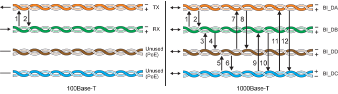
In multi-channel systems, it is a key parameter that determines the correct operation of the entire system. Analog signals, due to their gentle slopes, do not generate a large amount of interference, which is the source of crosstalk between individual channels. A completely different level of problem appears in the case of multi-channel digital transmissions, especially those operating in synchronous mode. The steep slopes of digital signals cause a large amount of harmonic frequencies that introduce interferences to adjacent transmission channels, to the power supply and to other interfaces. An example of such transmission is the Gigabit Ethernet 1000Base-T and 1000Base-TX networks, where there are 4 different transmission paths per one cable, of which many can converge in the server room. The surge arrester for such installations must have very high parameters that are not included in the standard EN 61643-21: 2004, but are important due to the length and density of the cabling. The figure below shows the number of mutual interactions in the 100Mbit and Gigabit Ethernet lines, which should arise as little as possible in the surge arrester.
Maintaining a low level of crosstalk in the arresters is a complex process that includes the selection of the correct components, the selection of the appropriate quality connectors, the correct circuit design technique and the control of their manufacture.
The best way to verify protectors for LAN networks is to perform comparative tests using specialized devices. The diagram below shows the test of the Ewimar surge arrester and the competitor's product.

Shortened result of Ewimar's protection devices test.

Shortened result of competetive company protection devices test.
Entire content of this article together with photos is the property of Ewimar Sp. z o.o. and is legally protected. Prohibition of copying and sharing in part or in whole, or use in publications and public presentations.