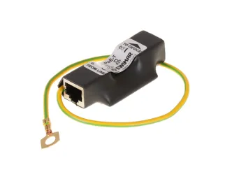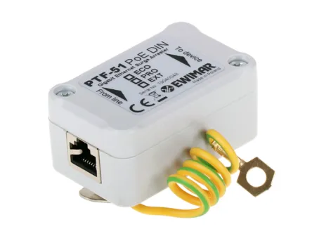
LAN surge protector mounted on DIN rail for IP camera, PTF-51-EXT/PoE/DIN
- Add feedback:
- Code: PTF-51-EXT/PoE/DIN
- Manufacturer's code: 5904041750397
- Weight: 0.1 kg
-
Availability:
 Produkt available
(shipping withing 24-48h)
High quality surge protector to 100Mbit LAN network, designed to IP camera and NVR, mounted on DIN rail, EXTREME series, PTF-51-EXT/PoE/DIN, manufacturer.
Surge protector, designed to protect one LAN cable against the effects of overvoltages and lightning discharges. It is compatible with 10Base-T and 100Base-T Ethernet networks, used in connection with PCs, CCTV camera systems, home and industrial automation as well as other consumer devices. It contains direct discharge to the ground of large surge currents individually from each conductor of the cable, without quite often used intermediary elements that reduce the strength for high pulse currents and have a huge impact on the emission or absorption of electromagnetic interferences.
Three surge protection stages in the Data pairs with the use of MOSFET technology, very effectively protects the delicate circuits of network interfaces and introduce an additional separation buffer, in case of high potentials between the LAN switch and LAN endpoints devices. In addition, the MOSFET technology reduces the level of voltages that reaches the protected device (UP voltage level) during the overvoltage to a value that is slightly higher than the rated operating voltage (Un).
Built-in power protection circuits PoE, eliminate the increase in voltage between transmission pairs 1,2 - 3,6 and 4,5 - 7,8 - which in 100Mbit networks are used only for PoE power supply. They have been grouped to simplify the protective circuit and one pair is treated as one circuit line. The PoE protection circuits protect the LAN end devices against damage due to lightning surges caused by lightning or uncontrolled voltage rise, for example as a result of damage to the PoE power supply. The solutions used are completely neutral for each PoE standard and protect each of them, including Hi PoE.
PTF-51-EXT/PoE/DIN is designed for installation in the vicinity of LAN endpoints such as: PCs, PLCs, IPC cameras, radio transmitters, Internet of Things. It is equipped with a housing with a metal holder for a DIN rail, by means of which a shock charge is discharged to the ground. For proper operation, it is necessary to properly ground using the PE line preferably as short as possible and separated ground point. The diameter of the earthing conductor must include surge currents discharged from all protectors mounted on the same DIN rail.
Follow the directionality operation of the protective function described in the operating instructions and do not reverse the connections of the device in the LAN system, which may cause it to malfunction or even damage.
PTF-51-EXT/PoE/DIN ensures the continuity of the FTP cable shield between the input and output and additionally discharges the surges between screen and ground. Because it is recommended to ground the FTP cable shield only on one side, the shield on the protector side during normal operation is galvanically isolated at 90VDC.
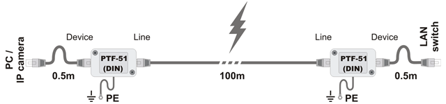
To protect one LAN cable , you can use two 1-channel surge protectors mounted on the two ends of the LAN cable and ground them accordingly. In case of necessity of securing many LAN cables, it is recommended to use multi-channel surge protector on the LAN switch side and single-channel on the side of LAN devices.
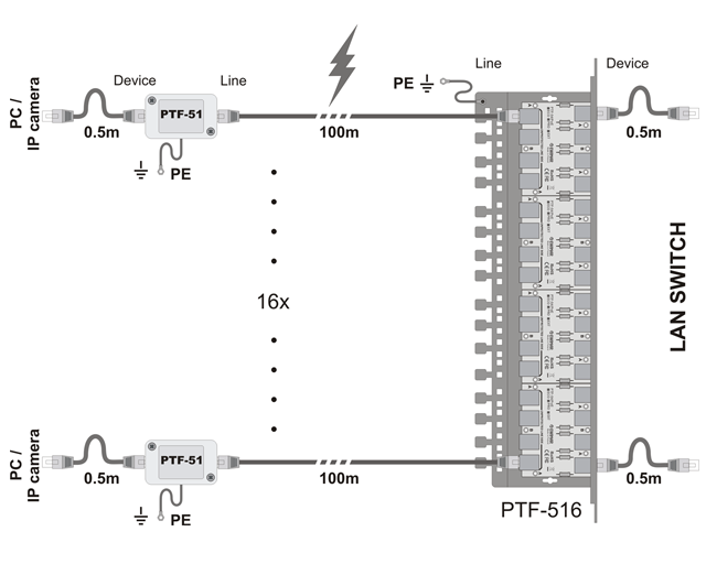
If an EXT series surge protector is used on the side of outide IP cameras, At least PRO series protector should be used on the LAN switch side, otherwise the protection of the LAN switch will be insufficient.
Surge protectors EXT series should not be used with standard patch panels with LSA (Krone) connectors should not be used because their PCB circuits have a little strength for high current pulses, and they will be damaged. If it is necessary to use a patch panel, it must be based on Keystone type connectors.
| PARAMETER |
NAME |
| Data lines | |
|---|---|
| Supported channels | 1 |
| Compatibility with Network | 10Base-T, 100Base-T, twisted pair 5-th, 5e, and 6-th categories |
| Input connector (Unprotected side) | RJ-45 |
| Output connector (Protected side) | RJ-45 |
| Rated Voltage DC (line-ground) UN | 90V DC |
| Maximum voltage (line-ground) UC | 110V DC |
| Protection level 1kV/μs (line-ground) UP | 600V |
| Surge current (8/20µs, line-ground ) Iimp | 2,5kA per one conductor of a cable (12kA total) |
| Rated Voltage DC (line-line) UN | 3,3V DC |
| Maximum voltage (line-line) UC | 3,5V DC |
| Protection level 1kV/μs (line-line) UP | 8V |
| Surge current C1 (8/20µs, line-line ) Iimp | 100A |
| Protected lines | 1-2, 3-6 |
| Capacitnance (line-line) @1MHz | 6-15pF |
| Capacitnance (line-ground) @1MHz | 1-2pF |
| Series resistance | 6Ω / line |
| Rated current IN | 300mA / line |
| Protection level | 3 (GDT, MOSFET, TVS) |
| Decouple element |
Super-fast MOSFET fuse |
| PoE protection | |
| Rated Voltage DC (line-line) UN | 57V DC |
| Maximum voltage(line-line) UC | 64V DC |
| Protection level UP | 93V |
| Surge current (8/20µs, line-line) Iimp | 0,6kA with MOSFET (option A), 250A (option B) |
| Surge current (8/20µs, line-ground) Iimp | 2,5kA |
| Protected pairs | (1+2)-(3+6), (4+5)-(7+8) |
| Protected PoE standards | IEEE 802.3af/at/bt-type 3 (HiPoE, UPOE) |
| Loss of PoE power in protection circuits |
IEEE 802.3af, option A: 0,6W @48VDC IEEE 802.3at, option A: 1,6W @54VDC IEEE 802.3bt, Type 3, option AB: 1,2W @54VDC
*) applies to full load |
| Common features | |
| Dimensions | 65 x 30 x 40 (mm) |
| Application | Inside, Outside in additional box |
| Mounting | Mounted on DIN rail |
| Housing tightness | IP40 |
| Operating temperature | -30ºC~60ºC |
Zakaz kopiowania i powielania treści! Powyższa treść zarezerwowana jest wyłącznie na użytek firmy Ewimar. Jeżeli chcesz umieścić produkt na swojej stronie, skontaktuj się z naszym Działem Handlowym w celu uzyskania treści ogólnodostępnej.